SELMER DIPLOMAT REVERB 15WATT AMPLIFIER - SCHEMATIC WIRING DIAGRAM


COURTESY OF JIM ELYEA, USA


POWER AMP CIRCUIT (See Note Below Diagram):

dip.jpeg - 131Kb

NOTE: This official Selmer diagram has been checked by Champ Electronics, and certain basic flaws found. These are as follows:

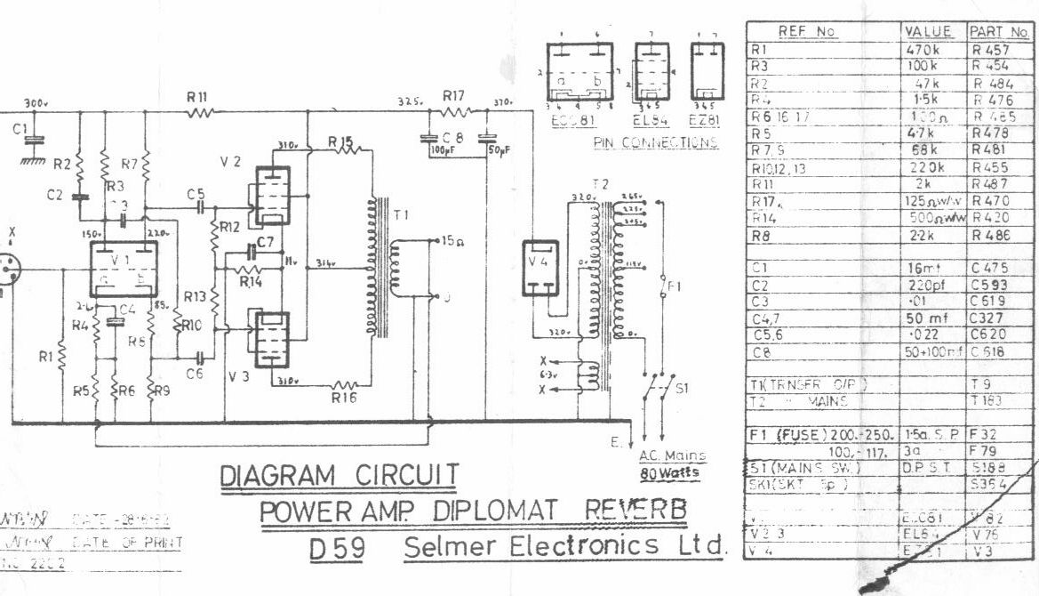
1. There should be an 8 ohm tapping on the output transformer.

2. Resistor R14 should be 125 ohms rather than 500 ohms as shown.

3. The right-hand grid on Valve V1 should be connected to the circuit between capacitor C3 and resistor R10.


Return to SELMER AMPLIFIERS - WIRING SCHEMATICS